
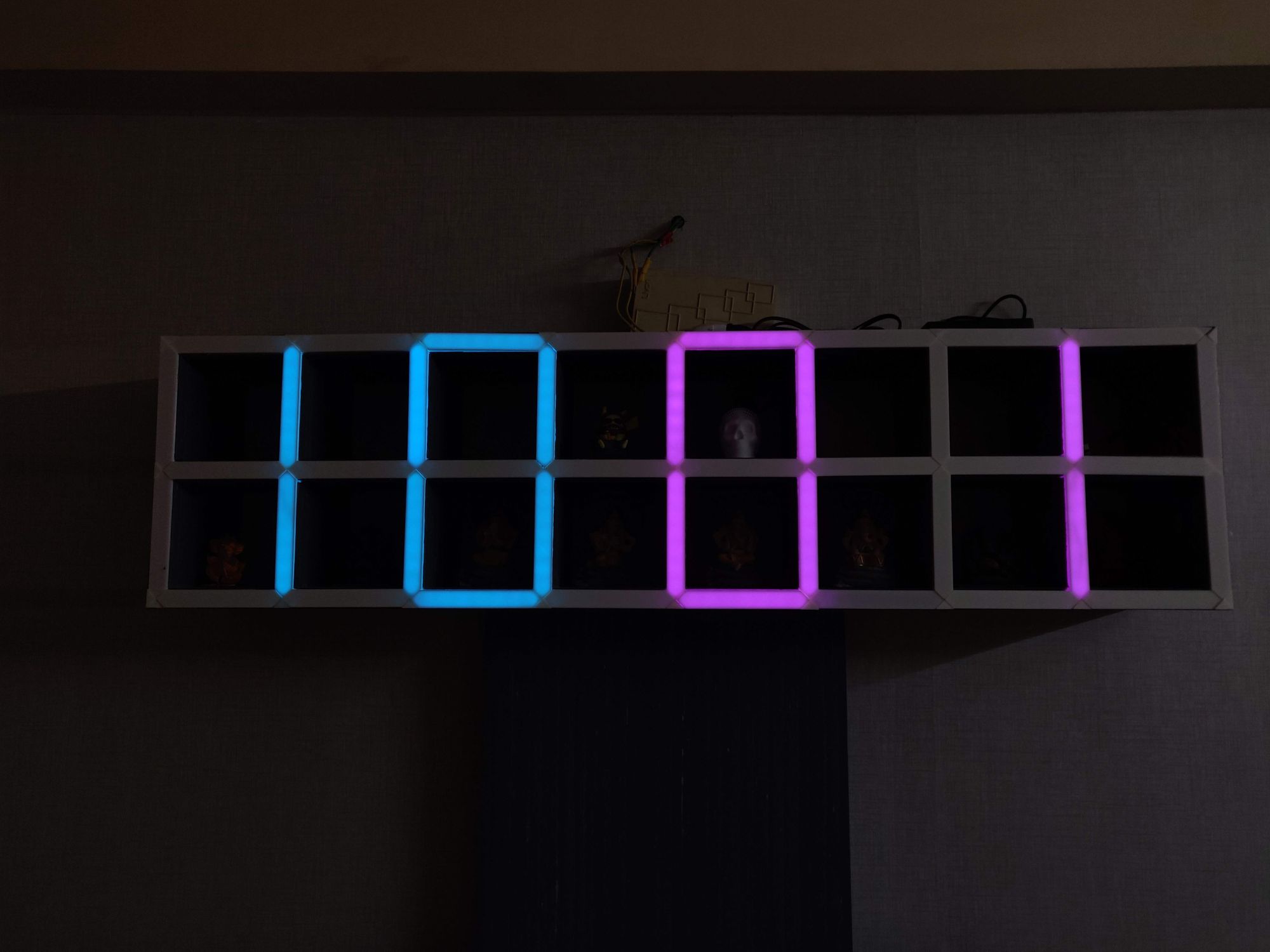
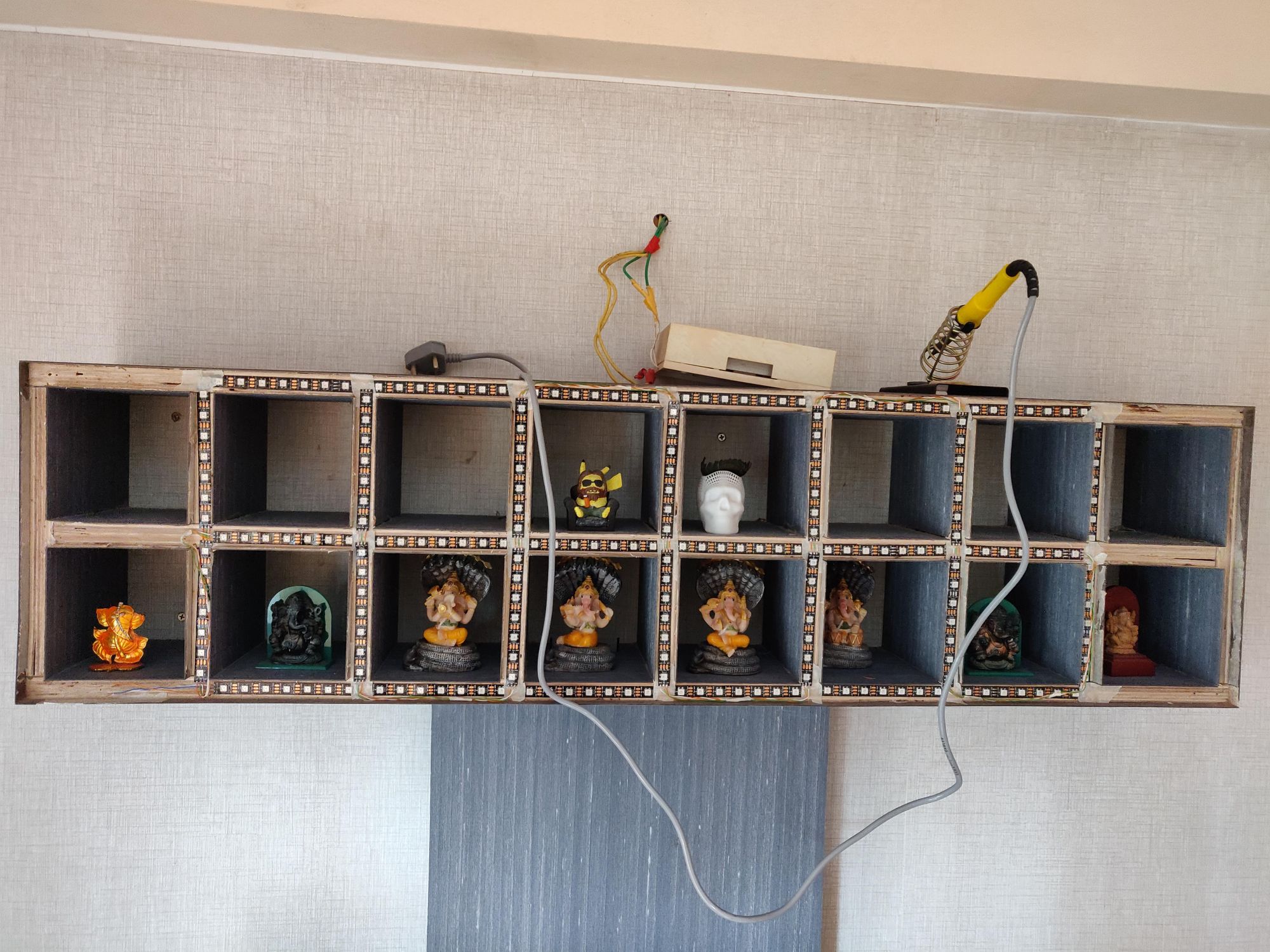
Here's a clock that feels like its built into the shelf itself. When the clock is turned off, it is an ordinary shelf on the wall. But when the digits start to show up, I like the reaction from people seeing it for first time 😊.
Carpentry
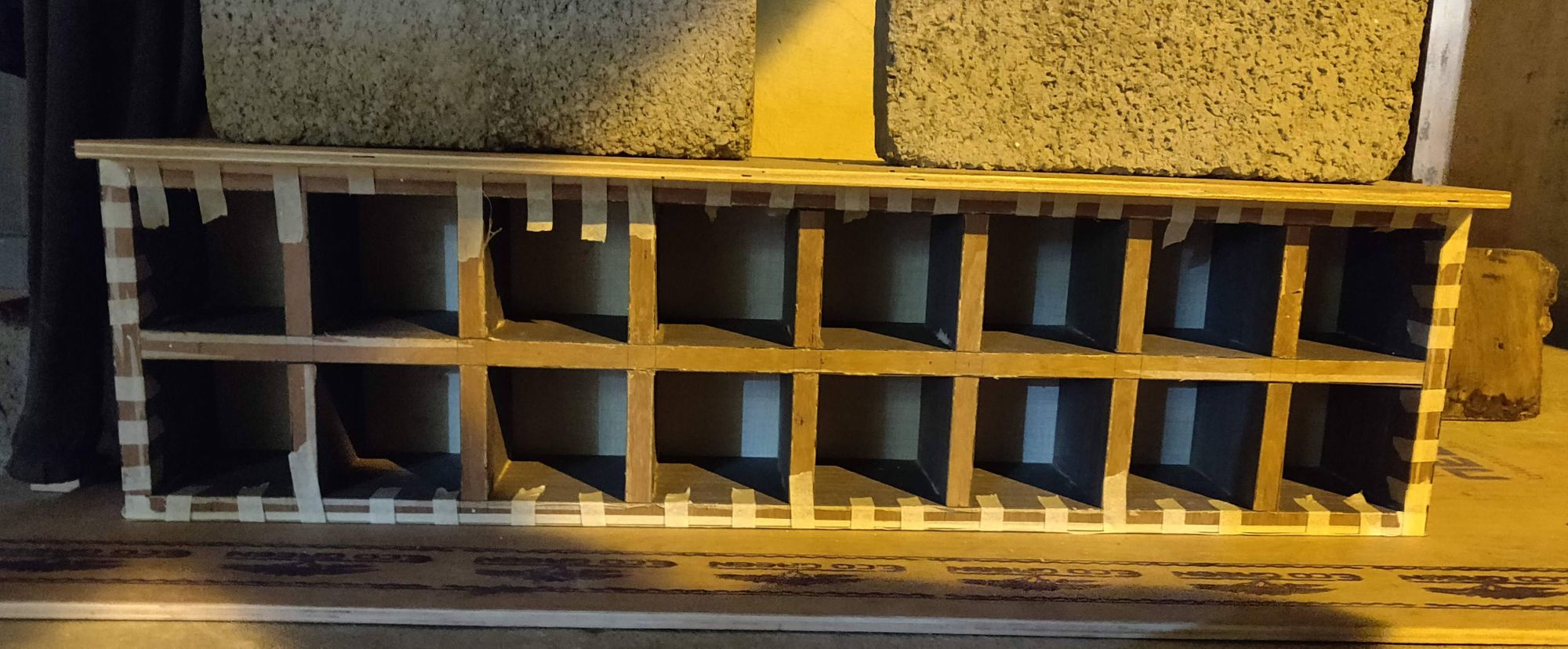
The dimensions for each compartment is 5" x 5". This is from mid point of the ply wood to mid point of the next one.
So the total height of the shelf will be 5" + 5" + 6mm + 6mm = 10.5"
And the length the came up to be 40". (and hence the size diff that we can see in the 3D printing section).
Designing the Shelf Edge for Digits
The Edges of the shelf will act as the individual segments of the digits (if you can imagine the digit in a 7 segment display). So each box/compartment should have a separate edge enclosure to reflect this.
Next the space between two such edges needs a filler to make everything look flush to the surface. And give an impression of an ordinary shelf. A small triangle is designed to fit this gap.
3D printing all the parts
The shelf needs total of 42 edge pieces and 24 triangle fillers to be printed.
But it those 42 edges some of them had to be smaller in order to adjust for the imperfections in the wood cutting and making of the shelf itself. I printed some 3mm lesser in length as and when the regular ones didn't fit.
Each Edge takes approx 1hr to print with 0.2 mm layer height. So thats 42 hours of printing just for these guys. I printed these over the week, in batches of 4 and some time between batch for the printer to get some rest 😅.
The filler triangle pieces have a fairly faster print time.
The Electronics
The electronics are fairly simple for this project. The main components use are -
- WS2812B
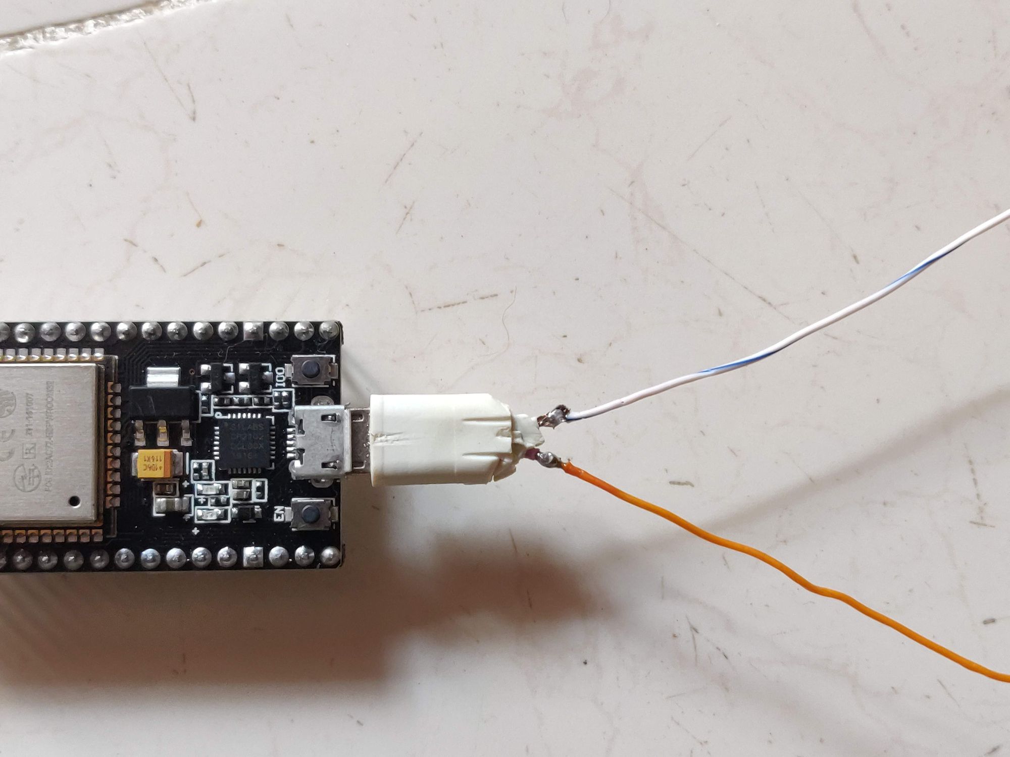
- ESP32
- Power Supply
The reason this is so simple is thanks to the individually addressable LEDs WS2812b. Without these, an Edge of the shelf or a segment in the 7-seg display of the digit had to be wired to the controller separately. And since most of the controllers will not have these many I/O pins, something like multiplexing or shift register should be used. This would have greatly increased the wiring and circuitry.
WS2812b is well tested and has good libraries written to abstract dealing with the data signals and controlling these ICs. In this project we will be using FastLED.
ESP32 is again my favorite low power low cost microcontroller with inbuilt WiFi and Bluetooth capabilities.
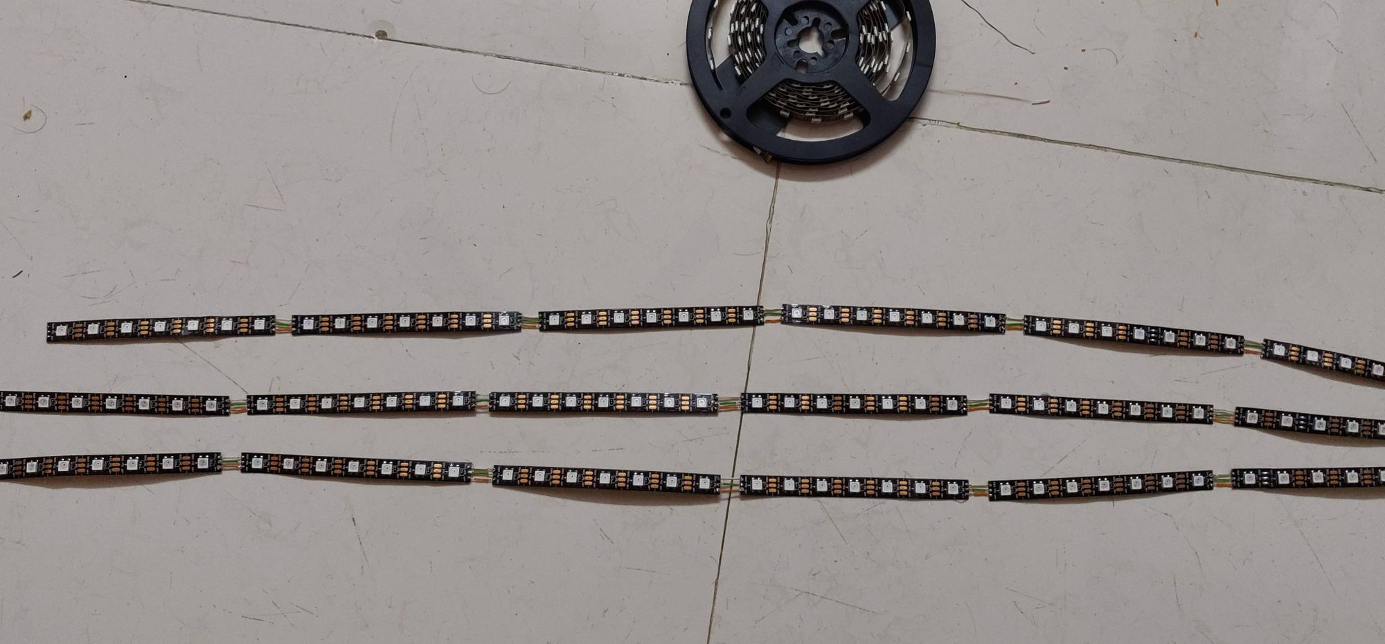
Step 1 - Cutting the strip into smaller pieces
I could not stick the LEDs in single long strip as this would result in LEDs being present inbetween digit segments. So I measured the number of LEDs that would fit in each of the printed edge and cut the strip into pieces. 7 LEDs per segment in my case (with 60/m strip density).
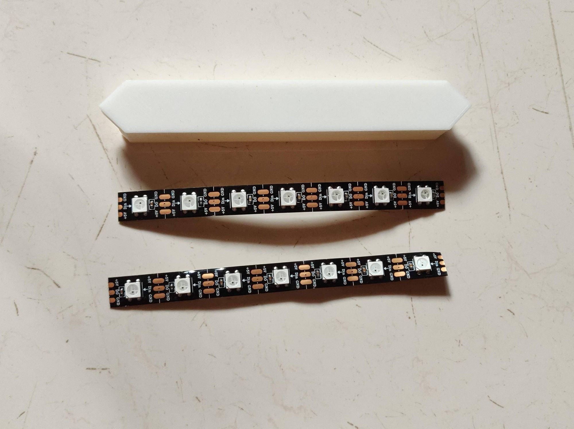
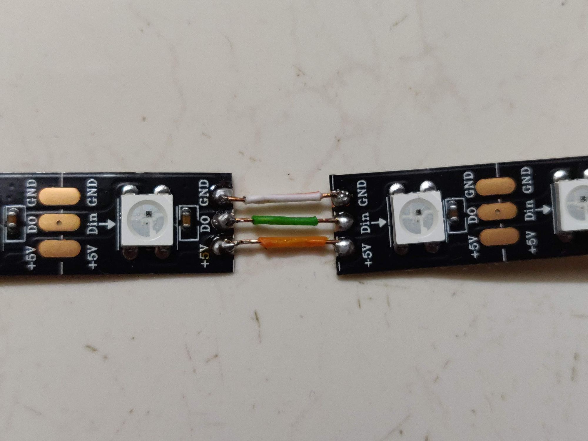
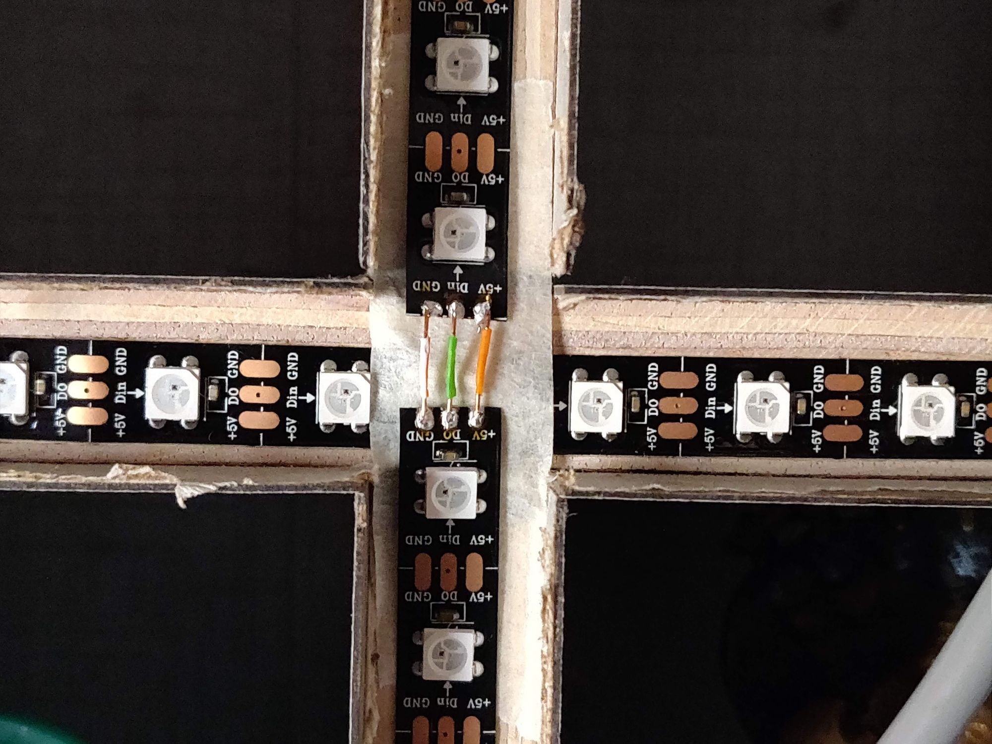
Step 2 - Soldering the cut strips
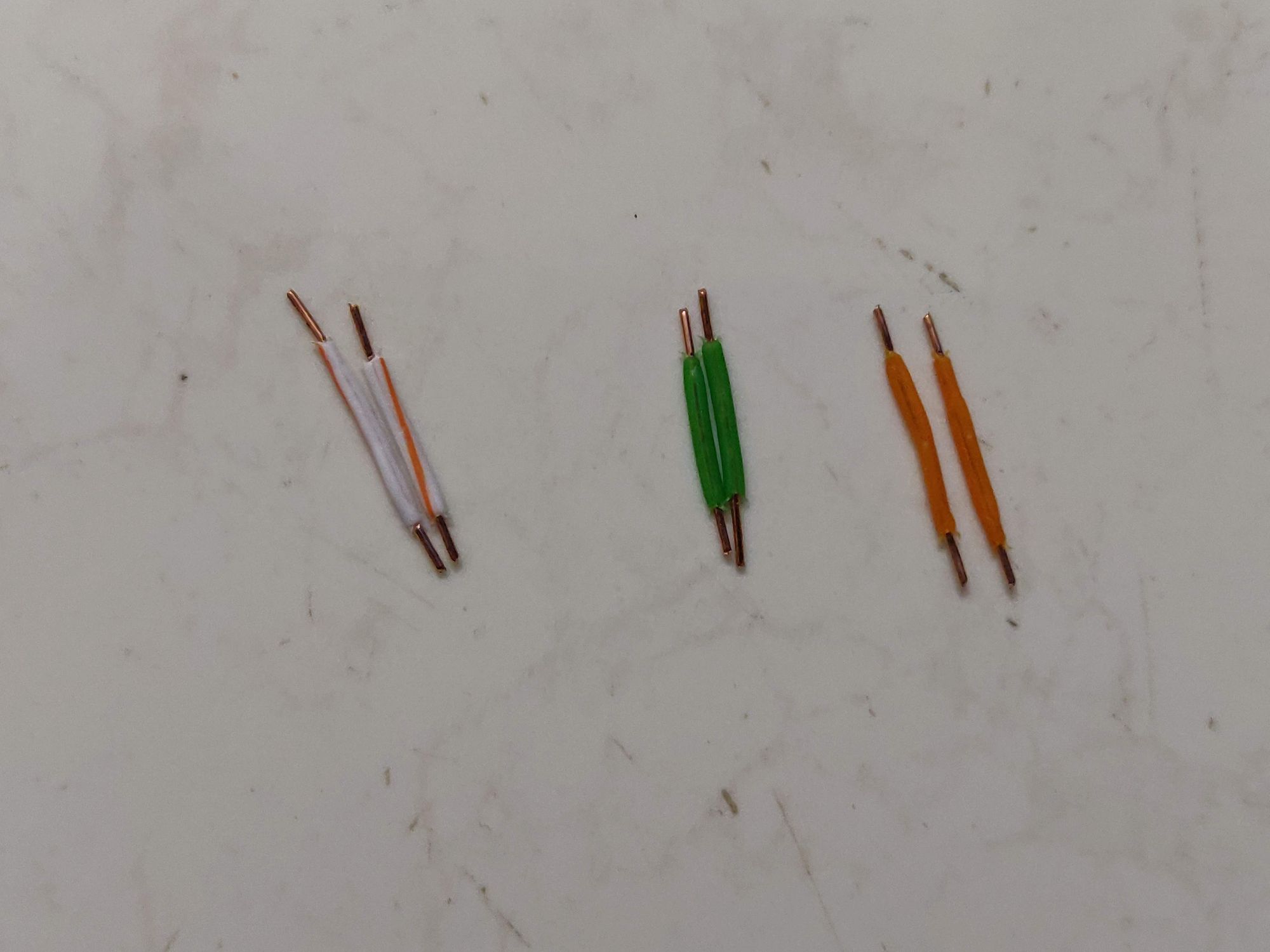
The strips for each segment are soldered with small pieces of wire of length equal to the distance between two segments on the shelf. This was approx 1.5 cm for me.
Step 4 - Sticking the strip and final soldering and connections
The Strip is finally stuck to the shelf and all the individual segments are soldered. I have made a wiring diagram for how I have soldered the segments for reference. The controller is added and the power supply connections are made.

Code
I am using this amazing code written by florianL21, checkout his repos for the shelf clock code. I have borrowed his code and modified it to work with my wiring schematic and my OTA update library.
In a very brief explanation, this is what the program does.
The controller is connected to the internet (via wifi). Since there is no RTC or timekeeping systems on board, everytime the board is started, it will ping NTP and fetch the correct time. Internal clocks on ESP can be used to update the time from this starting point, but periodically ESP will fetch time from the NTP servers to account for any drifts in the time (due to inaccuracies in internal clock). Next is taking care of display and setting the LEDs according to the time.
Since the LEDs used are RGB, any color can be set to the digits. And the ESP works with blynk to provide this capability, so that the user can change colors and adjust brightness anytime from smartphone.
I plan on adding other functionalities like integrating google assistant to show time by asking country wise, add a snake game and more.
Testing connections and first run
Done
**** इति लेखः समाप्तम् ****