
My First quad build. This is a QX95 based micro brushed motor frame, which is relatively economic and not powerful enough to damage property or chop off digits (and I still managed to cut myself when trying to fly this 😁). I my opinion it is better to start with something like this as you will at least crash once while learning.
Components and build
Main components of quad include -
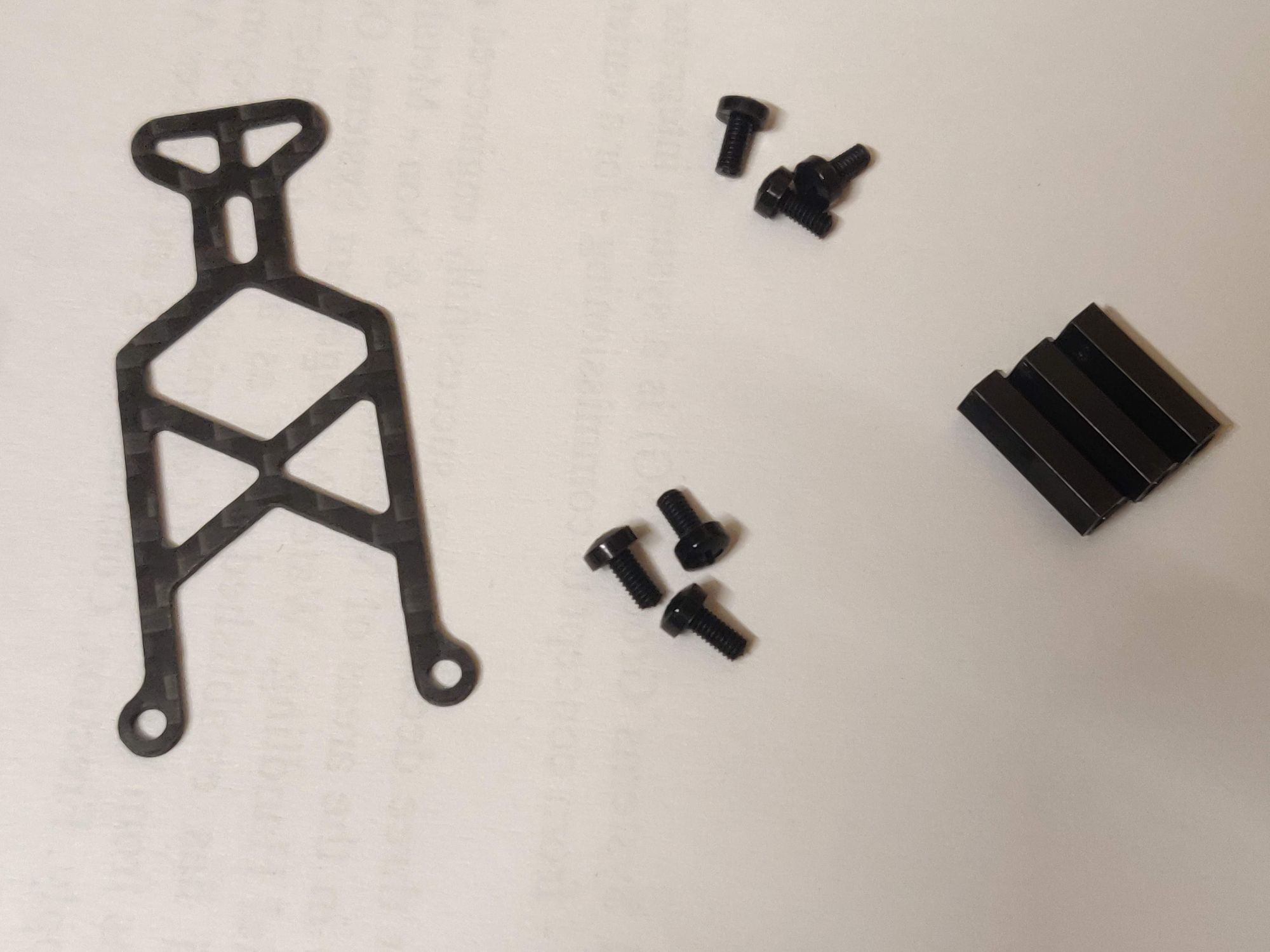
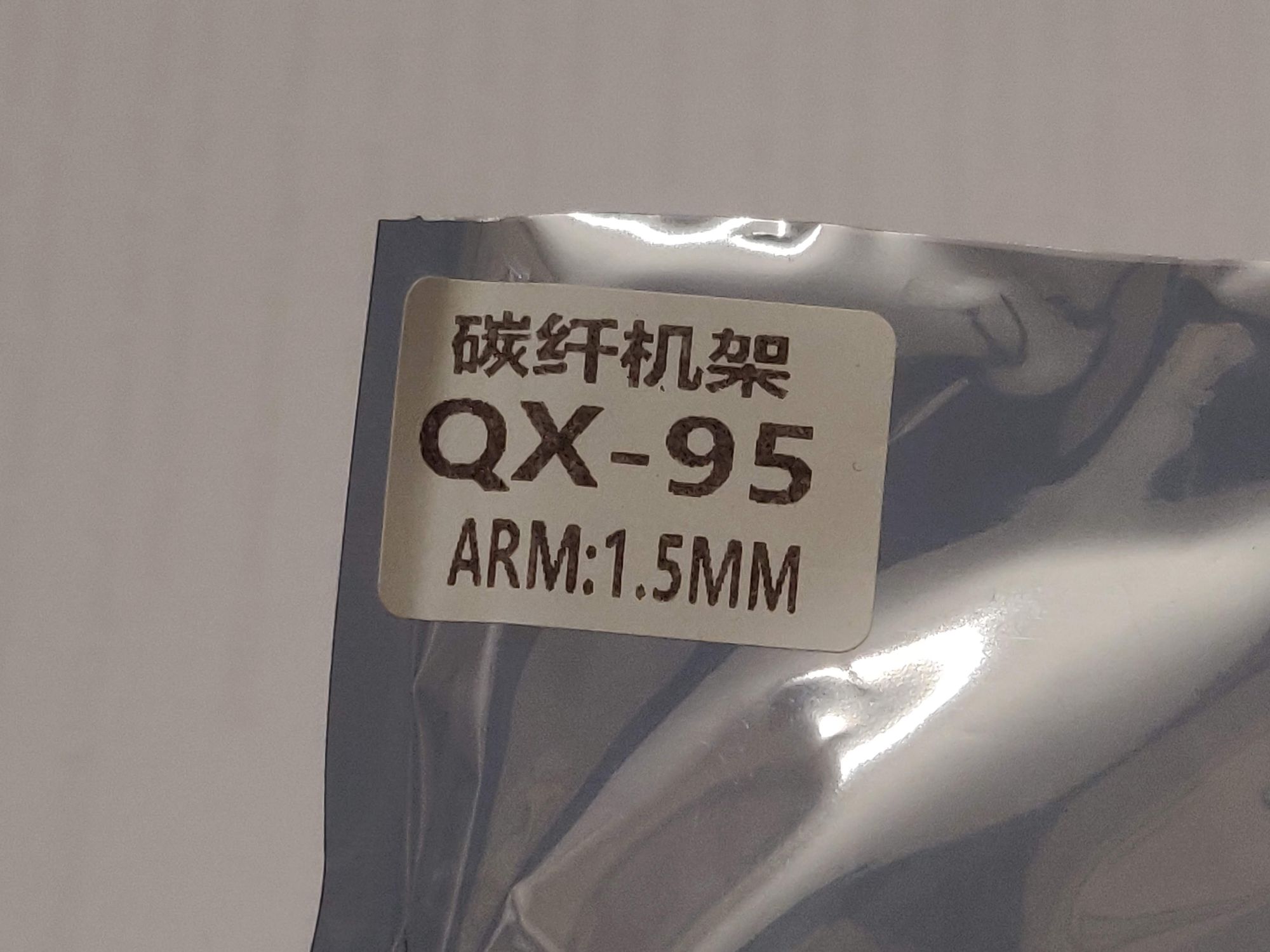
- Frame - QX95
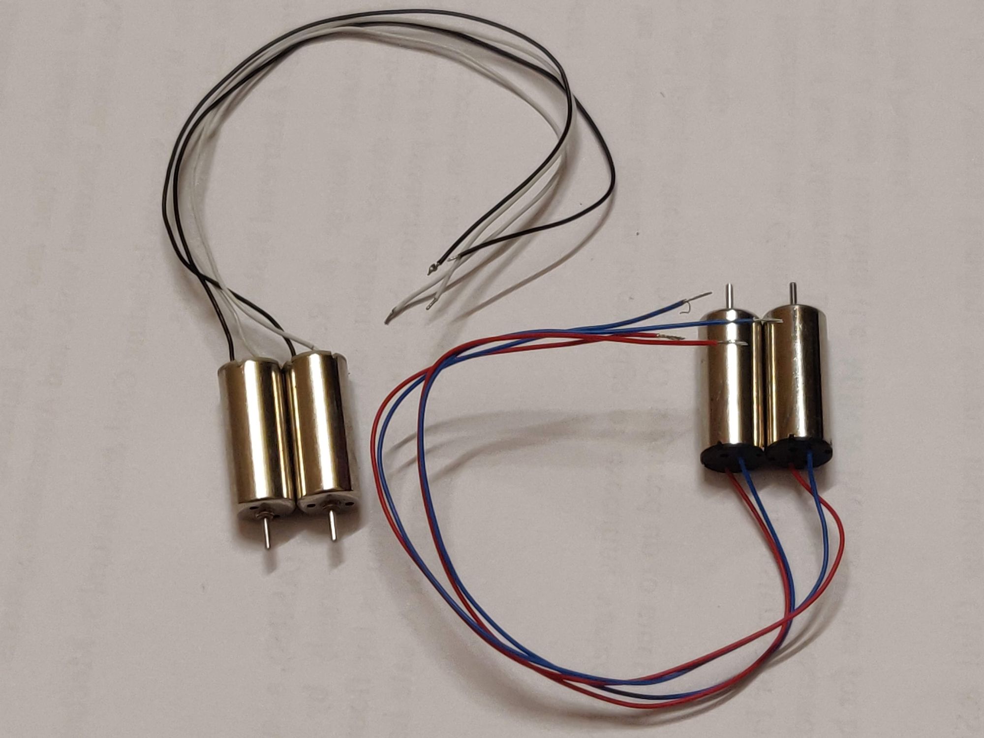
- Brushed/coreless motors - 2 x CW and 2 x CCW - 8520 Coreless
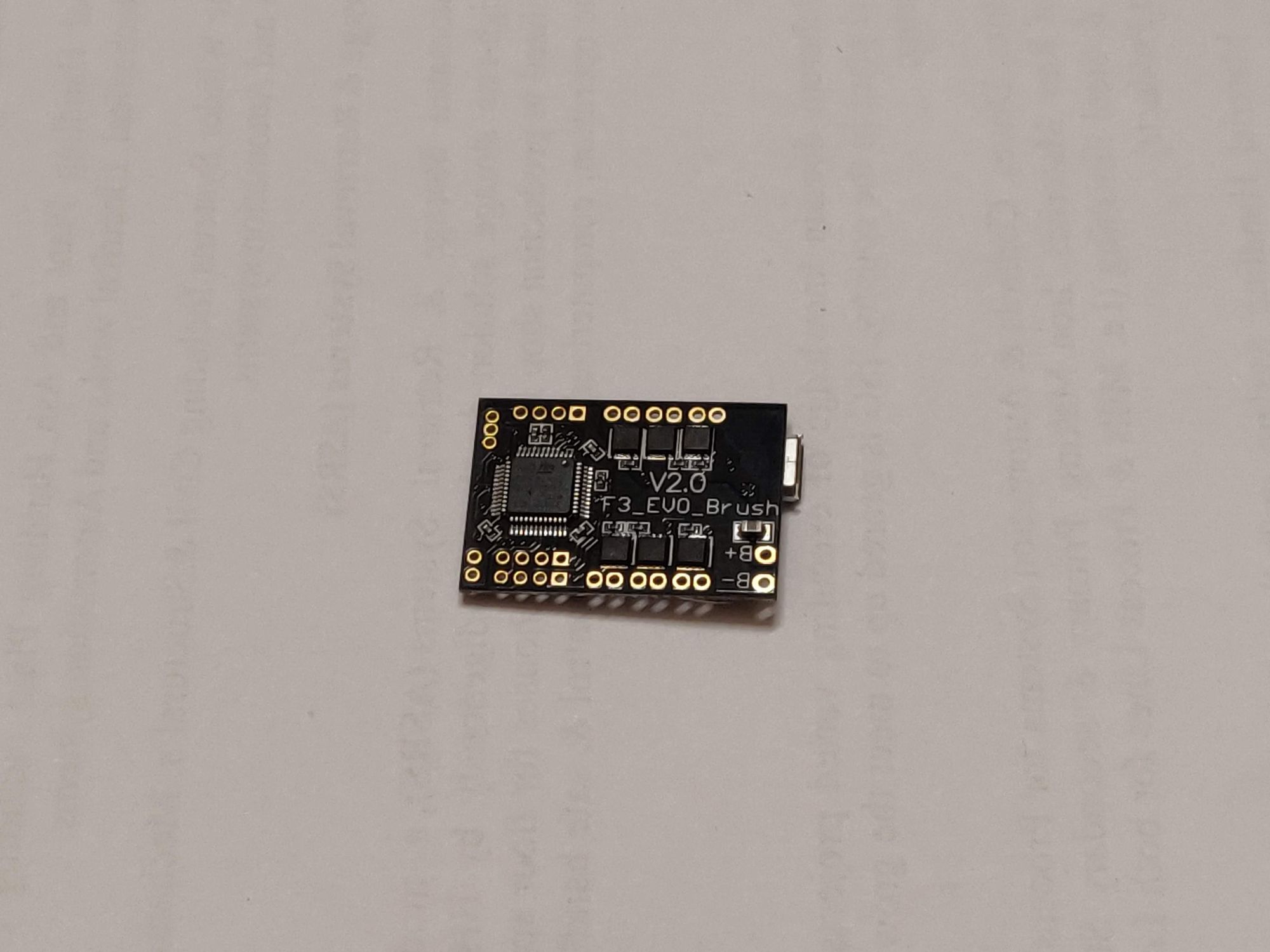
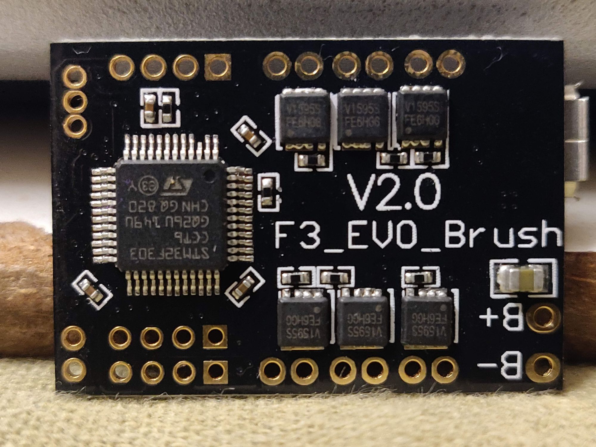
- AIO Flight Controller - (FC + Brushed motor controllers in a tiny package) - F3 Evo v2.0
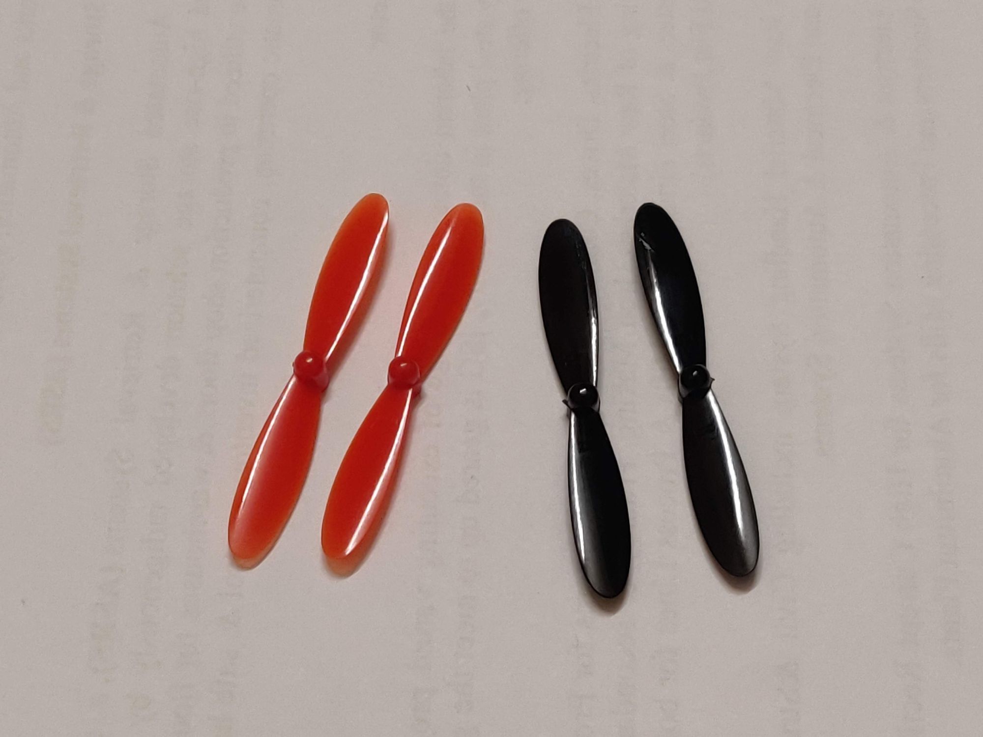
- Propellers - 2 x CW and 2 x CCW - 55mm
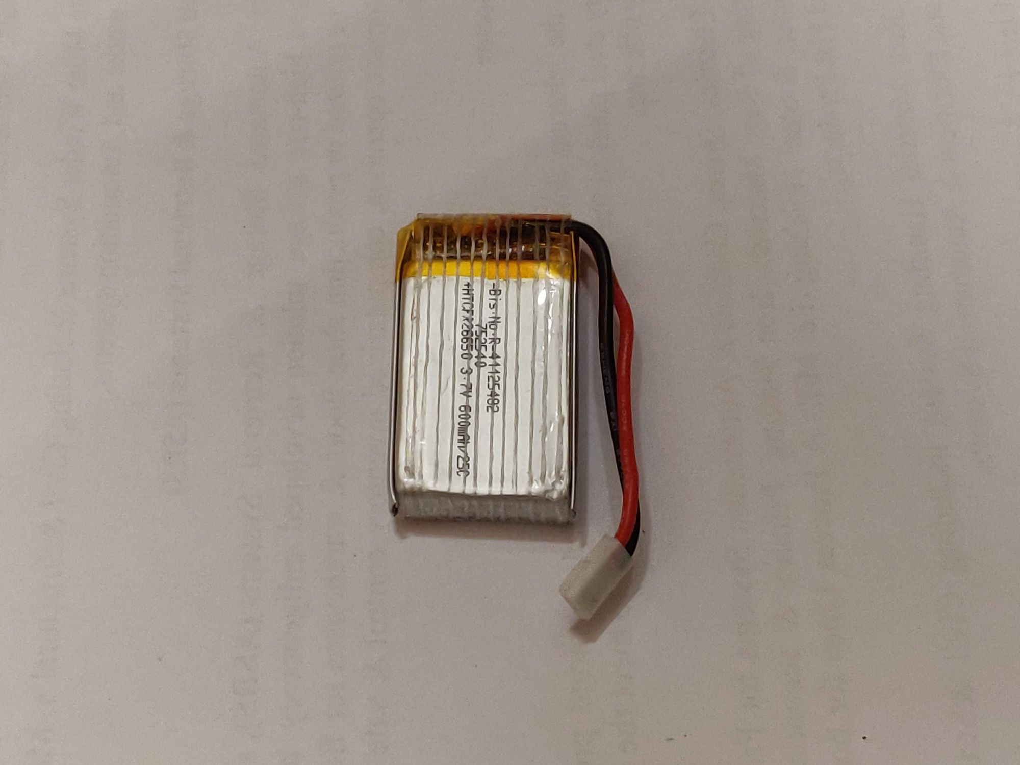
- 1S lipo battery - 600mAh 25C
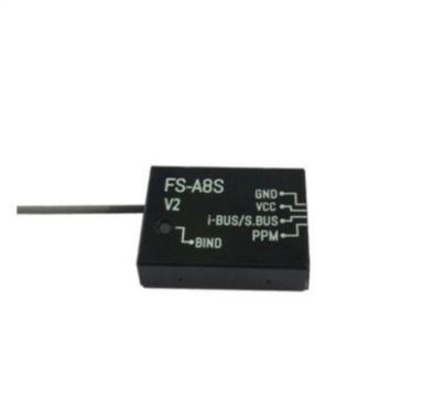
- Radio Receiver - FlySky FS-A8S
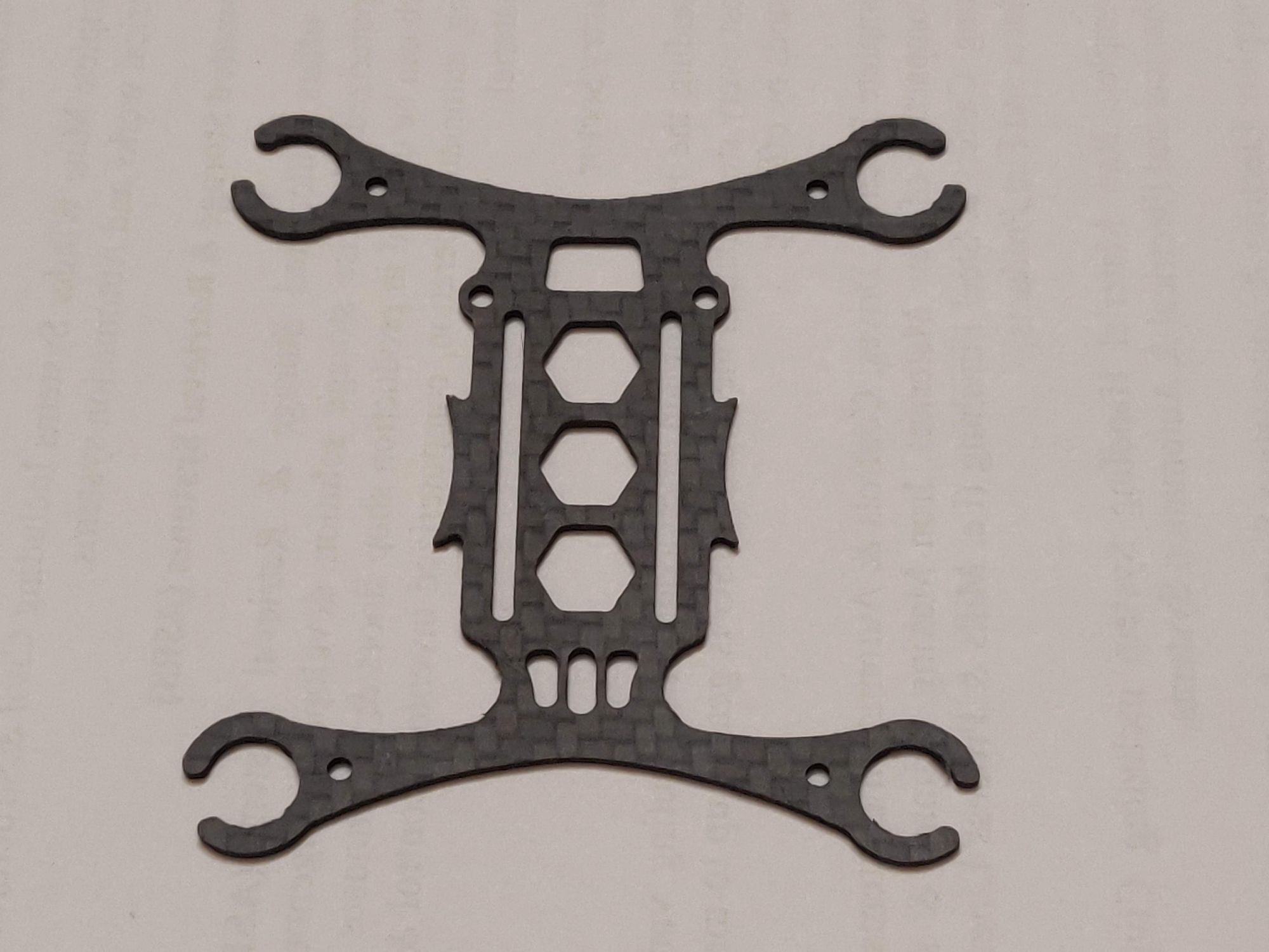
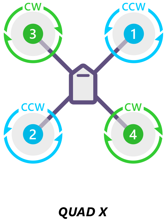
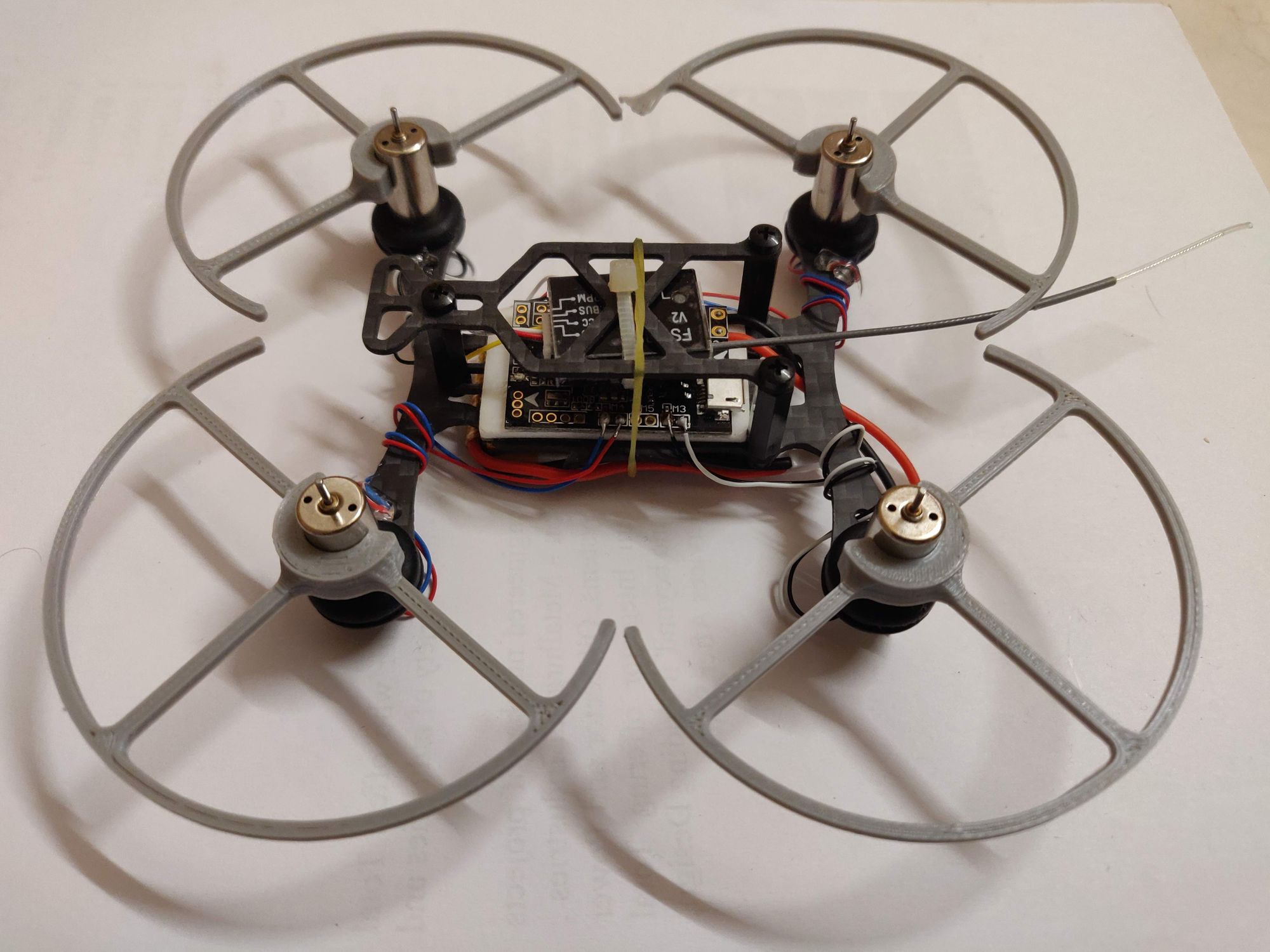
- The first step in the build process is to fix the motors to main frame. This goes with the rubber gaskets into the four arms. Important thing to keep in mind is the direction of frame - which is the front, and the CW - CCW motor placement. This is a X - config quad, so the basic rule of thumb is start with CCW at top right corner and continue alternating.
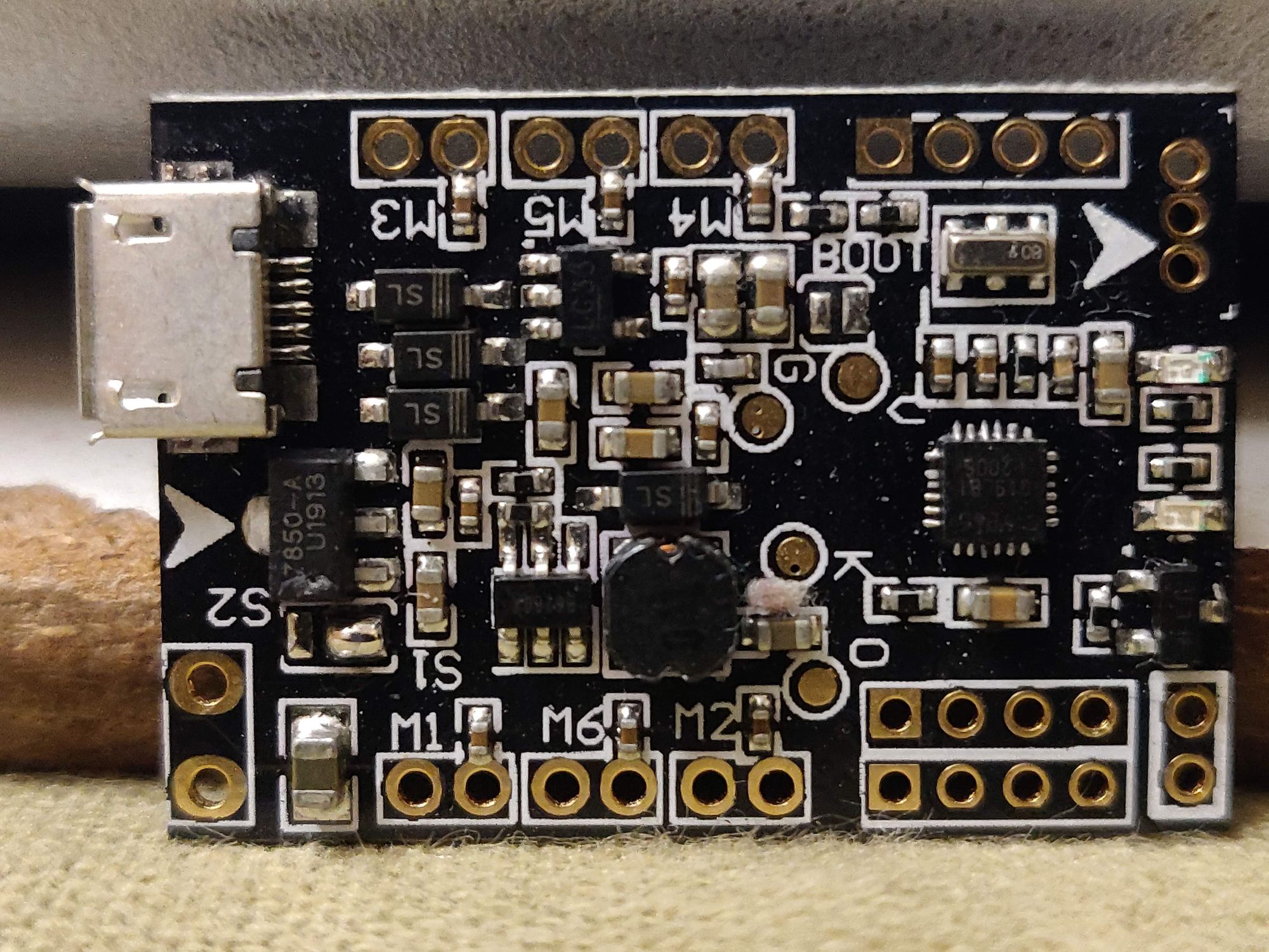
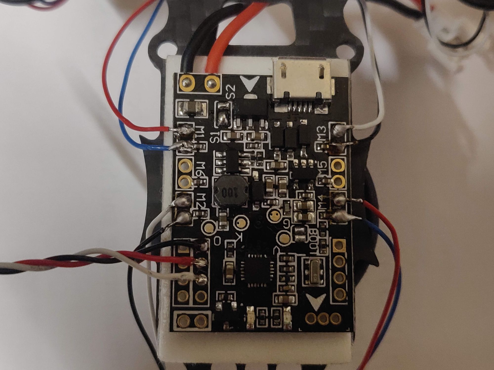
- Next is to secure the main Flight Controller to the frame. Make sure the right direction is facing forward. This is indicated by a arrow on the PCB and this should be pointed to the front of the quad.
- Solder all the motor leads to FC. I measured and cut wires to match the correct length so that they don't dangle or get caught in the spinning props. Wrap the wires few times around the arm. this way, in case you mess up the wire stripping or you want to move to different frame, you still have some extra wire to unwrap and use.
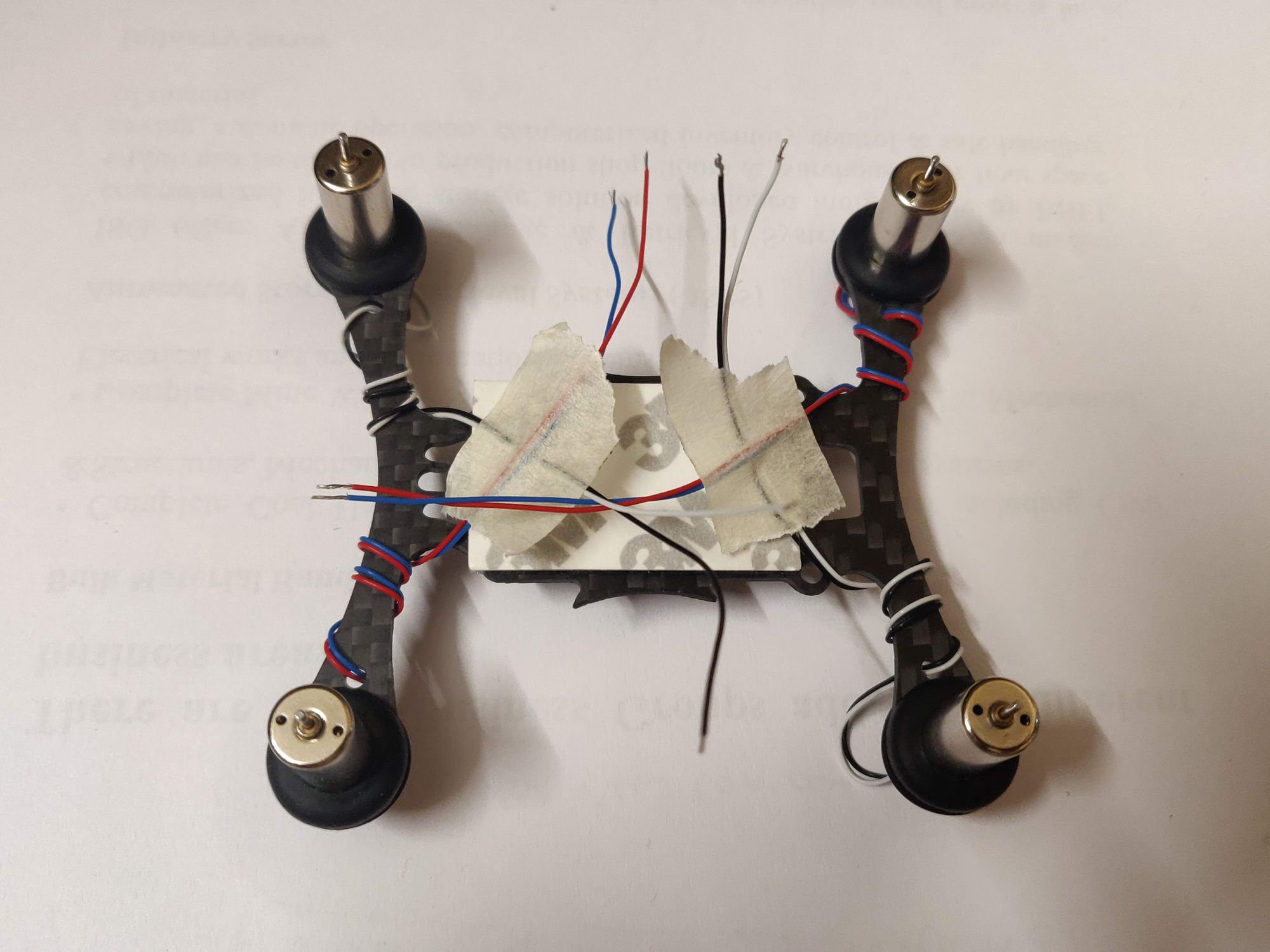
- One additional point I was not aware off, is that thee motors do have polarity. So for CW motor (Red & Blue) - Red is positive and for CCW motor (Black & White) - white is positive.
And on the FC, as you can see in the images above, each motor has two soldering pads. One of them has a passive component (should be a resistor) touching the pad and you should solder the negative terminal of motor to this pad on the board. - The four pad sets on the board are the UART ports. This one has three and can be used to connect any external modules. For this one I connected a Radio receiver in UART2.
- The final step in the build is to mount remaining top piece and secure the radio with a zip tie. The battery goes at the bottom and is kept in place with a rubber band.
3D print prop guard
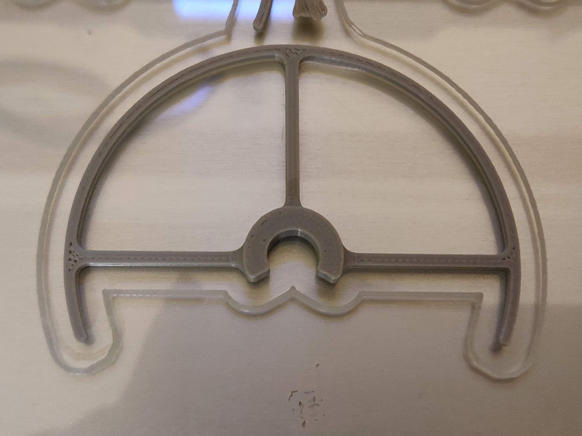
What's more expensive than the main build is the spare parts you'll need when starting to learn. To keep this to a minimum, I decided to find and print some prop guards for my quad so that even when I crash it into objects, I reduce the damage to props and motors.
Found this simple prop guard that can be printed for each arm and snaps onto the motor. It has a decent covering range and does the job to an extent.
Firmware and calibration
- The F3 Evo v2.0 comes with outdated Clean Flight firmware on it. First thing I did was to switch to the latest Beta Flight version available for this board. Both are very similar, but I think Beta Flight is actively maintained and new updates are available.
- For the computer to identify the FC board, right drivers have to be installed. Use Zadig to identify and install the USB drivers.
- The bootloader is locked by default on the board. To get access to it, the boot pins have to be jumped (there is a pair or solder pads labeled boot on FC, check images in above section). This can be done just by shorting the two pin when powering the board.
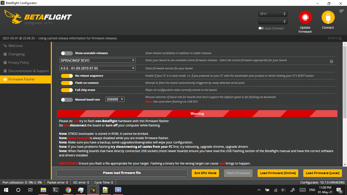
Note: should not solder these forever. Once the new firmware is flashed, these pins should not be in contact with each other in normal use. - There's a micro use port on this tiny board that is used to connect with the Flight configurator, in our case BetaFlight. To flash the latest firmware, make sure the drivers are installed and board is in bootloader mode.
In BetaFlight, select Firmware Flasher and select the right board from the drop down menu. At the time of flashing my board, the latest available was v4.0.6 for my F3 EVO.
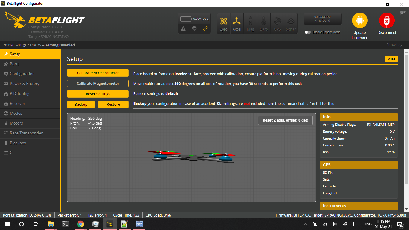
- On BetaFlight is flashed, disconnect the board and connect again, this time without jumping the boot pins. Now the configurator should detect the board on connect and you should see a simulated quad on screen that moves in sync with board movement.
- Next step is to calibrate the quad by placing it on a level surface and click Calibrate Accelerometer button in Setup screen. This will also clear up any laggy update of on screen quad movement wrt actual quad movement.
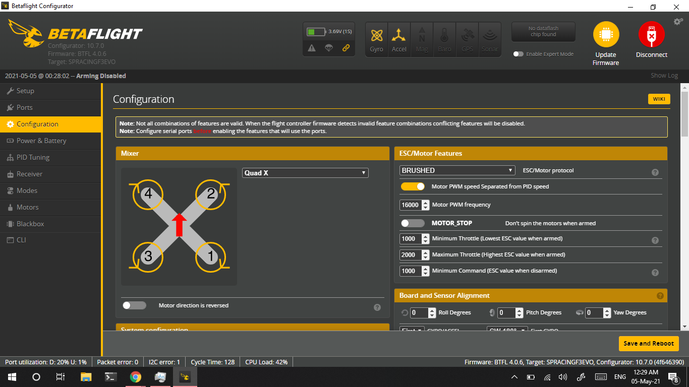
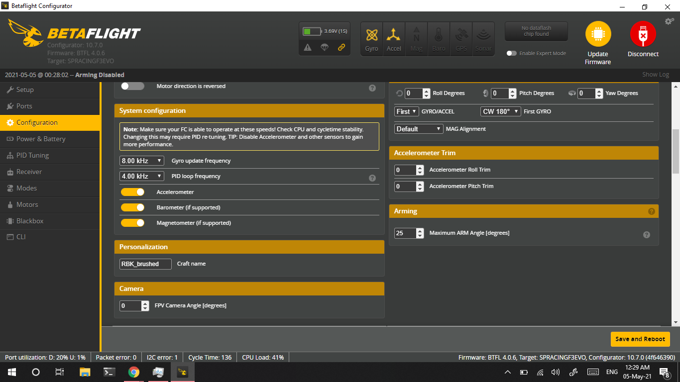
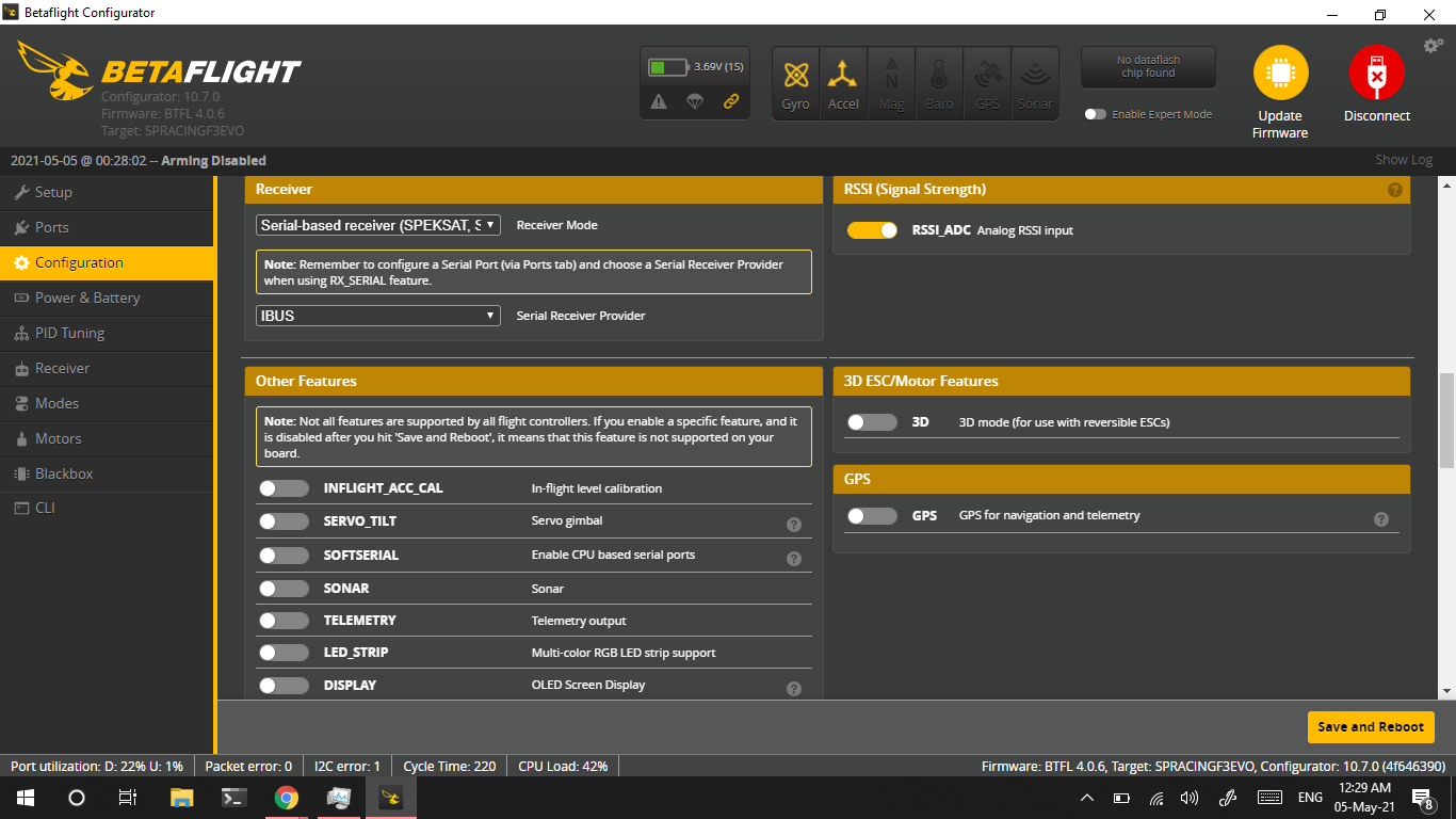
- Configure the Radio in Ports section to the connected UART on board. Then in Configuration section Receiver Mode and Serial type. In my case It is Serial Receiver - IBUS
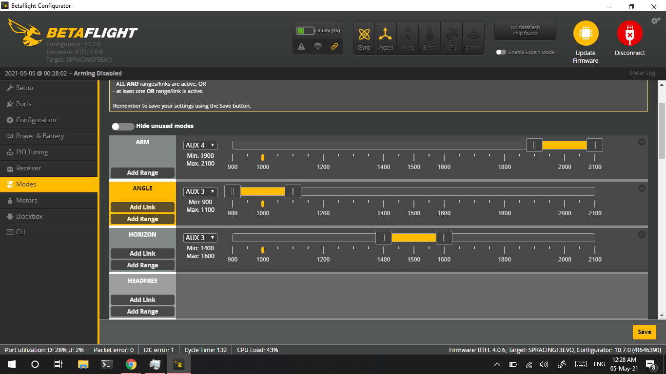
- Other main config is the Modes screen. Here I have enabled the Arming switch, Acro/Angle mode and Horizon mode.
Simulators and v-Joy setup
It is best to start with a simulator to get a feel of how the first flight will be like. Best both in terms of economic and safety reasons 😁. Get a hang of how the gimbals feel and how the quad reacts to different stick movements.
But the challenge I faced was that my FS-i6x transmitter did not work properly through the provided PS2 to USB data cable. Even though it was detected in the simulator software, it did not function properly as the stick ends were off and could not be calibrated.
This was fixed by using the FS-iA10B receiver and connected that to PC. This was transmitter can be used wirelessly to play in Simulators. The receiver was connected using FTDI board for TTL conversion between receiver and PC.
Next was to install required drivers to detect this receiver as a joystick device in windows. For this download and install FTDI drivers and v-Joy driver and v-Joy SerialFeeder.
Main videos I watched for building this quad
Lift Off
Charge the lipo, attach the props, pair radios, make sure all connections are proper, and lift off...